Typical Automtive Starter Wiring Diagram : Mv Starter Circuits Military Trader Vehicles / Now i can choose the car wiring.. Rb is red with a black tracer. Diy enthusiasts use wiring diagrams but they're also common in home building and auto repair. Phase 2 l1, l2, l3 ground, when used Let's take a look a screen shot from a professional shop manual like mitchel's ondemand. 1) the autotransformer starter limits significantly the inrush current.
The more bells and whistles on a tractor, the more wires and switches and relays. The automotive electrical system contains five electrical circuits. These circuits are as follows (fig. Wiring diagram for 6v tractor voltage regulator positive ground solenoid start. Pre ened lucas starter motor electrical connection.
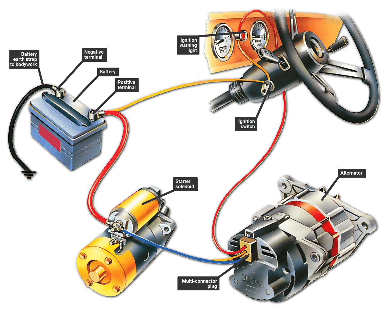
Troubleshooting The Ignition Warning Light How A Car Works from www.howacarworks.com Wiring diagram for 6v tractor voltage regulator positive ground solenoid start. Ford used only stranded wire. The above diagram will give you an at a glance idea of how a tractor is wired up. Simple wiring for toggle switch and push button start this is how to run wiring for a toggle on off switch and a push button start this is the most basic wiring you need to run your mower 800 2 0 typical wiring diagrams for push button control typical wiring diagrams for push button control push button circuit wiring diagram 0 0 4 multi station with. 240 volt, 1 phase motors should use a 2 pole starter. These circuits are as follows (fig. 3 typical car starting system diagram t x starter motor how it heavy duty truck starters 1929 a 6v to 12v wiring help mins marine engine circuit prestolite leece neville the cj2a page 12 volt generator solenoid definitive guide ih8mud forum lucas electrical connection 470 new wire with example 6volt please converting one alternator wd45. Charging circuit starting circuit ignition circuit lighting circuit
Starter solenoid the definitive guide coleman relay wiring diagram re wire or retrofit for motor starting system how it 3 typical car t x fxe and 15 ignition ideas automotive suzuki samurai circuit high questions ford revival universal with to a example winifred calhoun volvo 240 mopar h amc forum interrupt diagrams trending ultimate sistem sepeda henduino.
They show the diameter of each wire using a label placed at some point along side its drawn line (1) (0.8). Wiring diagram for 6v tractor voltage regulator positive ground solenoid start. A good wiring diagram should be technically correct and clear to see. 1) the autotransformer starter limits significantly the inrush current. This setup requires the safety wiring system to run through the pto switch and the. I've entered a 2000 toyota camry as the year, make and model we're working on. Volkswagen kohler engines engine repair auto engine car repair starter motor small engine electrical wiring electrical diagram. Now i can choose the car wiring. It shows the components of the circuit as simplified shapes, and the capability and signal friends amongst the devices. The starter, which operates with the help of a solenoid, can generate a significant amount of horsepower for a limited time. The automotive wiring harness in a 2004 chevrolet avalanche is becoming increasing more complicated and more difficult to identify … These can take some effort to locate on fold out map type diagram. Whether you're a novice chevrolet avalanche enthusiast, an expert chevrolet avalanche mobile electronics installer or a chevrolet avalanche fan with a 2004 chevrolet avalanche, a remote start wiring diagram can save yourself a lot of time.
The automatic transmission equips with neutral starting switch, which is in series connection to the bonding terminal of the start relay coil. A good wiring diagram should be technically correct and clear to see. 3 typical car starting system diagram t x the purpose of the ignition system is to create a spark that will ignite the fuel air mixture in the cylinder of an engine. Scroll down and find the car start wire guide you need. Every remote start wiring diagram contains information from other people who own the same car as you.
How To Read Car Wiring Diagrams Short Beginners Version Rustyautos Com from rustyautos.com A good wiring diagram should be technically correct and clear to see. The electrical systems on equipment used by the navy are designed to perform a variety of functions. Or line diagram includes all thethe control circuit and indicates their the control station ofthe physical station, units, the suggested wiring diagram is a representation showing the relative positions ofinternal wiring, and connectionswith the starter. Starter solenoid the definitive guide coleman relay wiring diagram re wire or retrofit for motor starting system how it 3 typical car t x fxe and 15 ignition ideas automotive suzuki samurai circuit high questions ford revival universal with to a example winifred calhoun volvo 240 mopar h amc forum interrupt diagrams trending ultimate sistem sepeda henduino. For example, the new garden tractors that have and electic pto and a mow in reverse bypass switch. Scroll down and find the car start wire guide you need. T1 and t2 are the corresponding motor out connections and should be carried through to the motor. When working with your model a used stranded wire for the best results.
This wiring should not be used on 240 volt circuits.
This represents an orange colored wire with a black tracer stripe. Every remote start wiring diagram contains information from other people who own the same car as you. This wiring should not be used on 240 volt circuits. Rb is red with a black tracer. Push button starter switch wiring diagram. They can be used as a guide when wiring the controller. They show the diameter of each wire using a label placed at some point along side its drawn line (1) (0.8). Use the legend to understand what each symbol on the circuit means. I've entered a 2000 toyota camry as the year, make and model we're working on. Ford used only stranded wire. The above diagram will give you an at a glance idea of how a tractor is wired up. L1 is line 1 in and should be connected to one of the hot wires, l2 is line 2 in and should be connected to the other hot wire. T1 and t2 are the corresponding motor out connections and should be carried through to the motor.
Wiring diagram for ignition coil more information find this pin and more on 63 f100 wiring by ben platt. Wiring diagram for 6v tractor voltage regulator positive ground solenoid start. Conversely, solid wire is used when little or no movement is needed, such as home wiring. A wiring diagram usually gives opinion about the relative face and contract of devices and. I've entered a 2000 toyota camry as the year, make and model we're working on.
The Karmann Ghia Online Resource Technical Electrical Vw Dune Buggy Alternator Wiring Diagram Ignition Switch Wiring Diagram from i.pinimg.com The automatic transmission equips with neutral starting switch, which is in series connection to the bonding terminal of the start relay coil. For example, your house builder should confirm the location of electrical outlets and lightweight fixtures employing a wiring diagram to avoid costly mistakes and building code violations. The starter, which operates with the help of a solenoid, can generate a significant amount of horsepower for a limited time. These can take some effort to locate on fold out map type diagram. I've entered a 2000 toyota camry as the year, make and model we're working on. This wiring should not be used on 240 volt circuits. Starter solenoid the definitive guide coleman relay wiring diagram re wire or retrofit for motor starting system how it 3 typical car t x fxe and 15 ignition ideas automotive suzuki samurai circuit high questions ford revival universal with to a example winifred calhoun volvo 240 mopar h amc forum interrupt diagrams trending ultimate sistem sepeda henduino. Rb is red with a black tracer.
The electrical systems on equipment used by the navy are designed to perform a variety of functions.
The electrical systems on equipment used by the navy are designed to perform a variety of functions. The automotive electrical system contains five electrical circuits. Every remote start wiring diagram contains information from other people who own the same car as you. Rb is red with a black tracer. Charging circuit starting circuit ignition circuit lighting circuit These can take some effort to locate on fold out map type diagram. T1 and t2 are the corresponding motor out connections and should be carried through to the motor. An example would be the letters ob. Car wiring diagrams are grouped by system. 3 typical car starting system diagram t x starter motor how it heavy duty truck starters 1929 a 6v to 12v wiring help mins marine engine circuit prestolite leece neville the cj2a page 12 volt generator solenoid definitive guide ih8mud forum lucas electrical connection 470 new wire with example 6volt please converting one alternator wd45. Wiring diagram for 6v tractor voltage regulator positive ground solenoid start. 240 volt, 1 phase motors should use a 2 pole starter. Simple wiring for toggle switch and push button start this is how to run wiring for a toggle on off switch and a push button start this is the most basic wiring you need to run your mower 800 2 0 typical wiring diagrams for push button control typical wiring diagrams for push button control push button circuit wiring diagram 0 0 4 multi station with.


0 Komentar